Libre office draw difference between two blue squares when a line is selected

Hi, I am very new to Draw. I am using Libre Office version 5.1.6.2

I am finding it difficult to adjust the end positions of horizontal and vertical lines that I am drawing. I am constructing tree diagrams and I find that I always need to keep moving them around and making them longer or shorter.

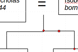
I select a line and then try and drag one of the blue squares that appear at the end points of the line to the desired position. This is not easy. The point often appears not to move and when I release the mouse button, the point jumps to the wrong place, or backwards, or even to the page margin.

One blue square is bigger than the other. Is that important?

Could I do this better?

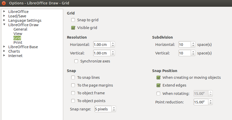
Below are my grid options:

P.S. I’ve added this image here as I don’t see how to add it to my comment:

image description

One blue square is bigger than the other. Is that important?

From my perspective, the larger square indicates the starting point and the smaller square indicates the end point of the line - just create a line from left to right (larger square is left) or from right to left (larger square is right). This is important to find which Arrow Styles (called Start style and End style) to change, if you need to add arrows to the start or to the end of the line.

The answer to your raw question is given by @anon73440385 in his comment.

The ragged positions of the points are a consequence of the Snap Position parameters (though curiously Snap to grid is not activated).

I’ll suggest a different approach. You are building tree diagrams. As you noted, it is difficult to draw a satisfactory diagram from scratch and the various components (nodes as boxes) need frequently to be reorganised for better look and cleaner structure. This means the arcs between nodes must also be updated to reconnect them to the nodes.

This can be automated.

Draw the boxes for the nodes as usual.

Instead of using lines or lines and arrows to connect boxes, use connectors (the tool icon shows two small boxes with a 3-segment line in-between). The drop-down menu allows selection of variants (straight or curved, with or without arrows, …). After activating the tool, hover over the start box, dashed “glue points” appear. Click on one and drag to the destination box, release the mouse button on one of the “glue points”. The connector remains selected with red adjustment handles.

When two boxes are linked with a connector, you can move them and the connector will follow, adjusting to maintain the relation.

To show the community your question has been answered, click the ✓ next to the correct answer, and “upvote” by clicking on the ^ arrow of any helpful answers. These are the mechanisms for communicating the quality of the Q&A on this site. Thanks!

Thanks, I’ll give that a try.

That works very nicely. Just one further question: Is there a way of making neat three or more way connections? I linked a box to the edge of an unbordered text and then tried to connect another box but couldn’t get the horizontal lines in line:

(oops, can’t add image here, so it’s been added at the end of my original question.)

To align correctly several connectors (to give the impression that all terminal segments come from a single wide horizontal line), take care that all all destination boxes have the same height (use F4 to access the properties and be able to force exact measures) and are all aligned so that their top border have the same coordinate (this is more important than the height itself). Adapt if your chart follows a perpendicular direction.

In your snapshot, it looks like you attached the selected connector (red dots) to the black connector. Don’t do that. Semantically, the box at right is attached to the = above. The connector translates the relation between objects: the left boxes has some relation to the equality above, so does the right box (otherwise its connector should have been attached to the left box. Attach bot connectors to the = sign (or its text box). Both connectors will then have the same geometry context and will be computed similarly. That’s it.

Yes. Changing it as you suggest works perfectly. Thank you so much.