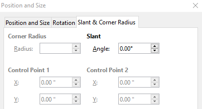
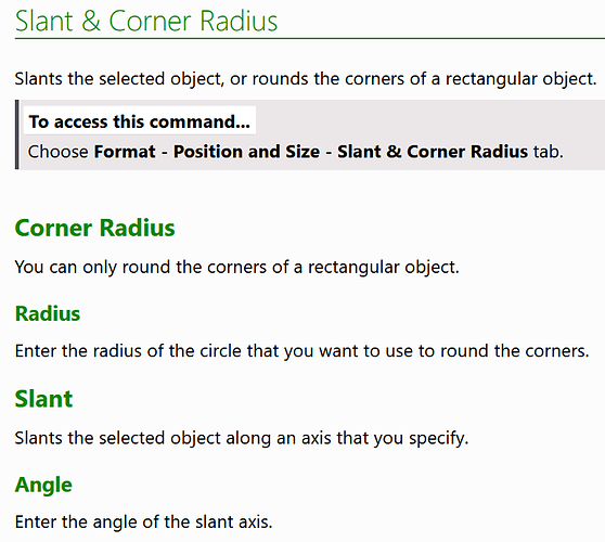
Short answer: Corner-Radius is not applicable to chart objects.
Corner Radius
Looking at file format: A draw:corner radius attribute is usable with draw:rect, draw:caption, draw:text-box and office:annotation elements. A chart is a draw:object element. Therefore it cannot have a corner radius. Not all options possible in file format are implemented in LibreOffice.
All objects, which are written as draw:rect elements in file format, are those, which are contained in the “Legacy Rectangles” toolbar. There exists rectangles too in the “Basic Shapes” toolbar. That are custom-shapes and do not have a corner-radius attribute. (If you are unsure, whether you have a custom-shape or not: If you can use the “Toggle Extrusion” command, then it as a custom-shape.)
The objects, which are written as draw:caption and draw:text-box in file format are those, which are contained in the “Text” toolbar. From those objects the simple text-box is so often used, that the command (icon T) has been included in other toolbars too. The presentation objects “Title”, “Subtitle” and “Outline” are text-box elements too, and can have corner radius. One exception is the Frame object in Writer. Although it is a text-box in file format, LibreOffice does not allow corner-radius for it.
The left top corner has a handle which you can use to change the radius with the mouse. You need to move the mouse a little bit around to find the active spot. For rectangles you need the point mode; the handle for text boxes is always available. If the radius is larger than half of width or height, you get an elliptical curve.
The office:annotation elements occur as Comment in Writer and Calc. Only the comments in Calc can show corner-radius, but LibreOffice does not offer an UI to set or alter the corner-radius.
Slant
“Slant” is for more objects available, because it is a transformation which is applied to the object after the object is constructed. It is a shearing were the horizontal middle line of the object is fix. The angle in the dialog is the angle from the vertical axis to the transformed vertical line of the object, with positive values result in clockwise angles. Shearing is written to file format as transformation matrix together with rotation, scaling and translation. There exists no mode to get this shearing with the mouse. In this shearing, the line between original point and sheared point is parallel to the middle horizontal line of the object. That is different from dragging the middle point of the frame rectangle of an object in rotation mode.
Control Point
A custom shapes can have handles to alter its outline, e.g. the handle to alter the mouth in the “Smiley” shape. Such handles can be dragged with the mouse. The part “Control Point” of the dialog allows to set the position of the handle as distance to the left-top corner of the frame rectangle (the rectangle with the resize handles) of the shape. “Control Point” means “handle” here. This feature was implemented in version 5.1, see https://wiki.documentfoundation.org/ReleaseNotes/5.1#View.2FEdit_Control_Points. The fact that there are exactly two control points is a compromise in order to be able to implement the feature at all with a reasonable effort.
The fields, which are not needed for a special shape, are disabled. So only the y-value of the first control point is enabled for the “Smiley” shape, because it has only one handle and this is only moveable vertically. Notice, that you enter length values too in case the handle is a polar handle as in case of the “Sector” shape.
Setting the position of a handle via this dialog works for most of the custom-shapes. Of cause those with more than two handles will not work for all handles. Some shapes, which are available in PowerPoint but not in LibreOffice will not work. And this feature only works on custom-shapes. You cannot use it to set the handles in an “Arc” shape of the “Legacy Circle and Ovals” toolbar.


