Size and Position won't stay the same - Draw

I am trying to draw straight lines that converge at one point. I select all the base points to be the same point, then I set the angle I want drawn, I get the pivot point coordinates where I want, I set the height, I set the width, I set the position, I check all the numbers again, and again, and hit OK, and then I look at the size and position again, they’re different. A few degrees, a fraction wrong on the height, the numbers aren’t the same and the drawing is slightly out of place. Also annoying that it cannot remember which point I selected as base point.

What can I do to effectively put elements where I want them and expect them to stay put? Why allow me to specify the size and position? I know I’m missing the big picture here… thanks

You “set the angle”. Between? How?
You “get the pivot point coordinates where I want”.
What’s your pivot point? The common point of your lines, or the point used in the ‘Rotation’ dialog tab for a single line or…?
Coordinates have values, not locations.
I “set the height”. Of what? How? Same concerning the width.
Where do you hit ‘OK’?
Too much of guessing.
Did you consider that the Position and Size... of a line describe the enclosing rectangle?
What snap setting do you use?

What do you finally want to achieve?

Generally you should create the lines as you need them (length, direction) disregarig the exact position, and position them finally using the snap feature.

Sometimes, it is the way you are used to working. If you are more familiar with CAD tools, you could try the extension CADLO

Sorry if that wasnt clear. Not using snap, as far as I know. I’m strictly using (position and size) dialog to set the position and base point (these are the terms used in that dialog), the size, the rotation angle. The HEIGHT and WIDTH are also terms used in that dialog. The “angle” is the “rotation angle” on the “rotation tab”.

Yes the pivot points are all the common point of my lines.
What I want to finally achieve is a basically a 12-point pie chart with detailed text on each sector, but I can’t get fontworks to flow text on the spreadsheet pie chart. I just needed help with values not holding still.

Not used to CAD tools, I may look into this.

Why don’t you use the pie chart tool? The only restriction seems to be a limitation to a single-line text on each sector. I couldn’t succeed to enter a line break in the cells of the data table.

If you use the “Rotation” tab to define/change the direction, you need to set the Pivot Point there in the appropriate way again and again. Next time you open the dialog it will again be set to center (default).
In different words: I don’t know a way to change the default.
Changing a rotation while an improper pivot point is set will move the end points.

If you don’t need the proceding urgently, change to more handy methods. If you are sure to need to go the described way more than once in a year, you should write user code for it - or pay somebody to do it for you.

Writing code is my kind of solution. I haven’t found a primer that speaks to my level yet.

Maybe turtle vector graphics in Draw might be of interest? Search for turtle in Help

I am trying to draw straight lines that converge at one point.

If you mean you’re trying to draw an open angle, the best tool for that is the polygon tool. It allows you to draw several connected lines. Double-click to terminate the sequence. If you double-click on the first point, you have a closed polygon.

To edit the “polygon”, select it and activate the points tool (F8).

If your goal is to draw a “flowchart” with the lines displaying the relationship between other objects, use connectors. Connector ends are bound to “glue points” on other objects. Whenever you move these objects, the connectors are recomputed to remain connected where you decided. Connectors have themselves glue points at their ends: they can also be anchor points for other connectors. Thus you can merge connectors at one point and issue a single connector from there to another object.

To show the community your question has been answered, click the ✓ next to the correct answer, and “upvote” by clicking on the ^ arrow of any helpful answers. These are the mechanisms for communicating the quality of the Q&A on this site. Thanks!

In case you need clarification, edit your question (not an answer which is reserved for solutions) or comment the relevant answer.

I was seriously wondering what the questioner wanted to achieve. If he (f/m) wanted an angle, why didn’t he tell so? If the idea of an angle drawing includes an arc for him, there should have been mentioned the number of lines: two exactly.
BTW: There is the shape type Circle pie (sector).

I could have laid out my goal, but it made sense to focus on one specific question (why aren’t my edits remembered) instead of throwing out background information like why I want my line exacty placed.

What I want to achieve is a pie chart (twelve sectors actually).
Perhaps circle pie sectors are a tool but every tool I try to use brings rabbit holes for more quesitons and frustrations and confusion. Keeping it simple!

I think you need to recognise that this package is grid based, and tends to round things up or down, when I use shadow on a text box and ask it to give a width of .075cm it rounds that up to .08cm because the grid accuracy won’t go below .1mm
If you need a technical drawing package I would look at freecad or something like that.

…you need to recognise that this package is grid based, and tends to round things up or down…

There seems to be a misunderstanding. The grid, if shown at all (Visible grid enabled), helps the user with positioning visually. Only if Snap to grid is enabled, positioning/resizing with the mouse works stepwise controlled by the grid. Having started a drag operation you can disconnect the mouse pointer from the grid by pressing the Alt key. Positioning/resizing by explicit entries in the Position and Size... dialog is never subject to the snap feature.

(Also consider the additionally selectable snap options.)

that’s useful info! thanks

I suspect that during selection there has been a slight movement of the mouse that has shifted the target object.

To test this without needing to select the object with the possibility of moving it, I drew a line vertically using Shift and then copied it. I pasted it, then using position and size rotated it about the bottom left corner by 25°. I pasted again and rotated in the same manner by 50°. I continued a further 7 times adding 25° each time.

Expanding to 3000% the lines all seem to converge exactly. In the screenshot at 3000% below, the division in the rulers at the edge are 1mm so a difference of a few hundredths would be noticeable.
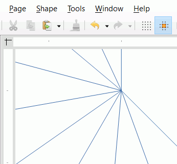
image description

I have attached the file ConvergentLines.odg if anyone is interested

2021-02-02 - pie chart with 12 slices

One way would be to draw a vertical (hold down Shift) line to the required diameter. Click it again to get the green rotation handles, copy and paste. Move the cursor to get the circular arrow at the top of the line, hold down Shift to constrain angle to 15 degree increments and rotate the pasted line 30 degrees. Copy and paste again, rotate again. Repeat. You should now have 3 lines crossing in the middle. Drag select all three lines, copy and paste. Without deselecting right click, Position and Size > Rotate about centre 90 degrees. Drag select all and Group

You could also draw a circle of that diameter, set fill to None. Shift select your group and the circle, Align Centre and Centred.

You could instead do pie segments

Note that pie segments are hard to put back into a circle if they are disturbed.

Ctrl+drag to copy your objects (just in case). Select Shape > Combine then Shape > Break, this will break the circle into 12 arcs. Elsewhere draw a vertical line (hold Shift) the radius length, copy and paste it. Right-click it and select Position and Size > Rotate, select bottom right corner and add 30 degrees to its angle, Ok. Drag the matching arc from your broken circle to snap to the ends of the lines. Drag select the three lines and in the menu Shape > Connect. You should have one piece of pie. Copy, paste and Rotate 30 deg, etc.

12ConvergentLines.odg

I tested your explanation and it seems to hold. Using keyboard-only, the values seem to stay put.