How to make colored opaque `Shape3DPolygonObject`?

This file has a set of macros to draw a Shape3DPolygonObject, with red lines and green sides. The colors are set in DrawPolygon3D.

DrawPolygon3D.ods (11.0 KB)

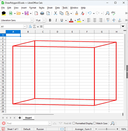
However, running the Main macro gives this:

The line colors are applied correctly, while the sides are transparent.

Editing setPLPoligon, to make the number of polygons 5 (0 to 4) instead of 6, like this:

Function setPLPoligon()
    Dim SequenceX1(4), SequenceY1(4), SequenceZ1(4)

    SequenceX1(0) = Array(  0, 100, 100,   0,   0)
    SequenceY1(0) = Array(  0,   0,   0,   0,   0)
    SequenceZ1(0) = Array(100, 100,   0,   0, 100)

    SequenceX1(1) = Array(  0, 100, 100,   0,   0)
    SequenceY1(1) = Array(  0,   0, 100, 100,   0)
    SequenceZ1(1) = Array(100, 100, 100, 100, 100)

    SequenceX1(2) = Array(  0, 100, 100,   0,   0)
    SequenceY1(2) = Array(100, 100, 100, 100, 100)
    SequenceZ1(2) = Array(100, 100,   0,   0, 100)

    SequenceX1(3) = Array(  0,   0,   0,   0,   0)
    SequenceY1(3) = Array(  0, 100, 100,   0,   0)
    SequenceZ1(3) = Array(100, 100,   0,   0, 100)

    SequenceX1(4) = Array(100, 100, 100, 100, 100)
    SequenceY1(4) = Array(  0, 100, 100,   0,   0)
    SequenceZ1(4) = Array(100, 100,   0,   0, 100)

'    SequenceX1(5) = Array(  0, 100, 100,   0,   0)
'    SequenceY1(5) = Array(  0,   0, 100, 100,   0)
'    SequenceZ1(5) = Array(  0,   0,   0,   0,   0)

    Dim Sequence As New com.sun.star.drawing.PolyPolygonShape3D
    Sequence.SequenceX = SequenceX1
    Sequence.SequenceY = SequenceY1
    Sequence.SequenceZ = SequenceZ1

    setPLPoligon = Sequence
End Function

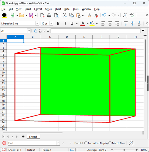
produces this changed result:

So it’s obvious, that the sides are actually colored, but something (orientation?) prevents the intended rendering.

Could someone suggest please, what should be done in the macros, to make the 3D body with all 6 sides green and opaque? @Regina, I am sure you know the answer! :slight_smile: Thank you!

Hi Mike, that is an interesting project. I do not know an answer out of the box. I have not used macros for 3D-objects but I have always worked directly in the file source. So I need some time to look into it and try it out myself.

In general there exist these problems:

  • A polygon needs to be closed to be able to be filled.
  • I think, a polygon needs to have all points in a plane.
  • A polygon has an “inside” and an “outside”. What is “inside” and “outside” depends on the point order. The “inside” of a polygon is normally not drawn. The polygon looks transparent then.
  • I’m not sure, whether using a polygon directly in the scene will work at all. If you save the file, the result has an empty scene. Currently a scene in ODF can have only cube, sphere, extrusion, rotate and scene child elements.

You should perhaps start much smaller with one plane polygon and no transformations.

And I would not work in Calc because it has no UI for 3D. That make is impossible to experiment with the rendering settings.

2 Likes

@mikekaganski, what is the final goal of your project?

@Regina thank you for looking at this!
This is not my project; I just help someone with their project. They have a very interesting use case, when they generate the 3d models based on data that is entered in Calc, and stored in a database. Hence, their sample was in a Calc document; and the end result will indeed be also there; but the intermediate investigation can be anywhere - it doesn’t matter, if it’s Draw.

The reply to your questions was (translated):

  • The polygon is closed. All points of a single face lie in the same plane.

  • I don’t understand what “inside” and “outside” mean, but I have experimented with the order of points. It didn’t help.

  • Saving is not necessary for the project. The objects are always generated anew from the data.

  • Calc is chosen consciously. The project is based on a database and table documents. The graphics are a side product, and a decoration, but still very important. Hence Calc.

By the way, I have compared all the methods of Cube and Polygon objects. A Polygon has several properties absent in Cube: xShape3D.D3DNormalsPolygon3D and xShape3D.D3DTexturePolygon3D, and they are empty arrays of PolyPolygonShape3D. Similar arrays are used to define coordinates of shape points. But these arrays are empty. Maybe that’s the problem? But I tried to put some figures there. It didn’t help.

The problem appears only when the polygons overlap. Then they become transparent.

I read somewhere, that this effect is sometimes associated with

xShape3D.FillColorTheme = -1

My gut feeling, independently from the person who asked me to help, is that there’s some bug here.

1 Like

@mikekaganski, perhaps you can forward my answer.

I have attached a document with some more macros for testing.
MakroTest with Library included.odg (19.9 KB)

FillColorTheme = -1 is unrelated. It simply means, that the color is not a theme color but directly set in FillColor.

I have made some experiments in Basic now. I have not looked were the relevant parts in the code are and therefore not really sure about all details. But my findings might help:

When you put two or more polygons into the Shape3DPolygonObject (Function setPLPoligon()), then the projection will have several polygons in the one 2D polypolygon shape too. And polypolygon shapes in 2D have even-odd rendering. That means, that if for a pixel the number of overlapping polygons to which this pixel belongs is even, than the pixel is transparent.

A plane in 3D has a front face and a back face. Which side is treated as front or back depends on the order of the points. When you put several polygons into one Shape3DPolygonObject the decision from the first polygon is used for the others too, regardless of their point order. Cube, sphere, rotation or extrusion 3D object from the UI are constructed so, that the front face of the facets are outside and the back faces are inside. As these are closed solids it is useless to draw the inside back faces. That is called “backface culling”. LibreOffice uses “backface culling” as default. It effects planes too, that are not part of the predefined 3D objects. The setting ‘D3DDoubleSided = True’ disables this backface culling so that the backface is rendered and you see it.

I have seen in my experiments, that scenes with Shape3DPolygonObject are unstable in regard to rotations with the UI. If such rotation is wanted, you should use an extrusion object for each polygon. If you set the extrusion depth to zero it will behave similar as a polygon. Only that this polygon is defined on the xy-plane and other positions have to be done by transformations on the extrusion object.

In theory you should be able to group several of ‘one polygon’-objects into a scene, so that they can be transformed together. Such scene is then a child element of the outer scene. The file format allows this, but I have not tested whether it really works.

You have set the ambient color to White. That means maximal intensity for the ambient color. The edges of the objects are not visible then in case the line style is set to NONE. A 3D-effect for the user arises from the lights. To make them effective it is better to use a darker ambient color.

The chart2 module makes heavy use of the UNO for 3D-scence in the 3D variants of the charts. You can look there and see how the objects are used.

There exist some properties which are only implemented for special purposes in chart2 or are only used for a special kind of 3D-object. D3DNormalsPolygon3D seems to be one of these.

The support for 3D in Basic is weak, there exist not even all the properties in the SDK documentation. But it is important for us to know, that these 3D features are really used. Because there are plans to adapt the whole 3D implementation for better interoperability with MS Office, and thus larger changes are likely, it would be nice if you write bugreports and enhancement requests, so that we get a user view on the 3D features.

Kind regards,
Regina

3 Likes

I see mainly the problem with the feelings. The images have one strong property → excite some feeling(s) when you see it. But I cannot say the human perception is adapted for the feelings that arised from seeing the artificial 3D images. And 3D images excited different feelings than classical 2D images.
For example when you see the photo of some food, maybe you will have the feeling like: nice meat, I also would like to eat it etc. → but the essence is, mostly you will have at least some words for the feelings from 2D images, and these feelings you can also feel in reality.
But are you able to feel the feelings arised from 3D images also in reality? Or only when you see the 3D images?


3D images and animations can be easy tool to cause the “new” feelings in user(s), but these feelings aren’t reproducible in normal reality.
You showed the 3D model of some barn, and I suppose I’m not alone who have some interesting or zesty feeling from seeing this 3D image, furthermore when I tried to vision how could look the real building based on this 3D model. But I’m sure, I will never feel this feeling in reality; and I’m also sure if I will see the real building based on this model, my feelings will be different.
But you exampled the images that is easy to imagine in reality, barn or hall or shed, so the margin (difference) from the feelings from 3D image and real images isn’t so big; and there is big chance you will have the words for these feelings.


But are you sure the people are always will find the proper words for the feelings from different 3D images? It is possible to experience some partially strange or mysterious or uneasy or apprehensive feelings for example from other 3D images, but you will no able to find the proper words to named these feelings. And it could be big problem.
For example some partially strange feelings I have when I see the 3D robots generated by some AI ChatIdiots. These images aren’t the results of statistics of probability algorithms, it is result of work of neurological measurements, hard work of many programmers and printmakers, of course to get more moneys for big tech firms → based on new feelings gotten from these images. And partial fear is able to get next money, frightened people are easily manipulated.


The problem is, if you will experince some strange feelings, are you sure it will be easy to delete these feelings-without-words-for-ones from your inward?
If you absolved some psychotherapy, probably you now how super or loosen is if you will find the proper words for some problematic feeling you feel.


And I’m sure you know the classical daily dreaming, probably you are also thoughtful in some situations that are in your head more times in day. You imagine some situations and feel some feelings from this imaginations. But probably you have the words for the feelings from these situations, because it is based on real images.
But what do you mean will happen, if you will imagine the 3D images in daily imaginations or daily dreaming? Will it stay really innocuous? Or it will causes the feelings that will experince only you and nobody else? Of course maybe absolutely without the words for it? It is posssible to construct some new words for strange personal feelings, but will it be able for explanation to other people? Will be somebody able to understand you or your problem? Artificial feelings based on artificial imaginations, heavily personal feelings, no-communicable and no-shareable with other people.


So I’m man who decided I will not interested and support the 3Ds.

I took a look.

Short answer: You also need to set the plane normals if you want it to be filled.

Long answer: That drawing::PolyPolygonShape3D (or internal: E3dPolygonObj) is raw tooling - and intended to be. Compared with the used (e.g. UI/load/safe) I added it to be able to do potentially ‘everything’ in 3D by adding any PolyPolygons, including 3D coordinates, Normal per point and 2d texture (u, v). There is even (not reachable via UNO API) one color per 3d Coordinate for interpolating nice gradients following the form of the polygon). I am pretty happy that I added it to UNO API at that time :slight_smile:

But UNO API works by creating an empty object and then setting the data. While there are methods CreateDefaultNormals() and CreateDefaultTexture() in E3dPolygonObj these are not used in that case (they have no data to do the job, e.g. no geometry → no normal calculation). Thus the normals have to be provided by the user.

NOTE: This shape will not triangulate the given data by purpose so beware what you do - all 3D coordinates HAVE to be on a plane, else rendering might look strange. This is provided for performance reason. If in doubt, create one such object per triangle (the smallest guaranteed plane 3d shape).

The basic idea is:

  • if you just want 3D lines (that’s what you currently get), set the 3D coordinates
  • if you want it filled, set a plane normal in each coordinate. NOTE: This would be the cross product of two non-equal, non-zero vectors on the plane the geometry is defined on. NOTE: That’s what CreateDefaultNormals() would crate. NOTE: AFAIR there is a fallback to set just one normal and the rest is assumed to be equal if there are mre 3D coordinates than normals. NOTE: This is for each 3D coordinate and does not have to be the plane normal - bending these is/can be used for smooth normal interpolation/shading, e.g. make it look like a sphere segment, but without tesselating the geometry too much
  • if you want complex fill, also set texture coordinates. NOTE: Needed as soon as more than a color is used, e.g. gradient/bitmap, … NOTE: these are 2D (u,v) unit coordinates, but per 3d coordinate

Additionally the SdrObject/XShape stuff needs to be set correctly to fill the shape.
If you want to do more fancy stuff like bezier meshes I would suggest to implement in the C++ core and add API for it to set the data.
HTH!

2 Likes

Thanks for the comprehensive answer. I guessed that the whole problem is in the D3DNormalsPolygon3D and D3DTexturePolygon3D arrays, apparently filling these arrays is what the methods do
Create Default Normal() and Create Default Texture(), but I didn’t figure out how to use it properly. I tried to enter different data into the D3DNormalsPolygon3D and D3DTexturePolygon3D arrays, up to an array of point coordinates, but I did not get any result.
Could you use an example here to show what data needs to be entered into these arrays or how to use the CreateDefaultNormal() and CreateDefaultTexture() methods correctly so that the polygonal cube is filled correctly.

when you use UNO API CreateDefaultNormals() and CreateDefaultTexture() is not available, that is C++ core code. But you can check in the C++ code what these methods do - you need to do the same in principle.
The normals should be vectors perpendicular to the plane defined by the point data, also normalized (length of that vector is 1.0).
The texture coordinates can be defined as you need in (u, v) coordinates. Usually these range from [0.0 … 1.0], so [0,0] is the top-left of the texture, [1,1] the bttom-right. Dependent of what you define the fill will be projected based on these coordinates.

1 Like

Thanks you!

If you want that the cube is one object, then you can use an inner scene to group the faces to a cube. The attached example has such cube. Create the scene with method Main_GroupedCube in module Main_Scene of Scene3D. You can enter the scene and rotate the cube as a whole without affecting the axes. My cube has no top and no bottom, so that you can look into the cube. The fill is a little bit transparent, so that you can see the axes and the edge of the cube. The example shows further how to calculate the normals.
Normals.odp (21.7 KB)

1 Like