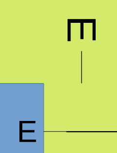
How to create this [connectors with named ends]

I’m trying to draw sort of a map… like this brief example:

Right now, I’m created the NSEW as individual text boxes, then putting them as needed into the square, then connecting the squares with a connector, and finally grouping the initials and the square. I want to be able to drag each square around to position it, which is why I’m grouping them. But it’s a real pain.
I was thinking about whether I can create some kind of connector that has N and S on each end, respectively, so I can just use that to connect to squares, and then also E and W. But so far, I haven’t seen any connector that I can do something like that.
Does anyone have any other ideas of how to do something like this?

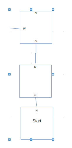
Once you have created the first group (and named it for ease if identification later) why don’t you just copy that by copy and paste or Ctrl+Drag?

[Edit]
Note that subsequent copies will use the original name but will be automatically numbered at the end, e.g. if first shape is named NESW, then the first copy will be NESW 1, and so on

1 Like

I guess the point is to have an efficient way of working with a large number of “location boxes” on your map, so that they “spontaneously” show the direction indicator when a connector is attached in that direction.

Alas, I have no good solution at this time. Thought I’d post my interpretation of objective anyway, to tease more avid minds than mine.

If there are only two connectors in each square, you only need six different squares: NS, NW, NE, SW, SE, WE.
Add the letters (N, S, W, E) as label to the shape. And copy & paste (or better, see @Grantler comment). You can edit the label to add “Start”, “End”, etc.
map shapes.odg (9.7 KB)

You can create the shape with the four letters, and then convert it to Polygon: you will get a group. This is your template shape.
Paste as many times as needed. Then you can enter each group (F3), and delete the non needed letters (exit the group with Ctrl+F3).
You can also enter and exit a group with double clicks.
map shapes 2.odg (12.0 KB)
You can insert text (start, end) to the polygon by selecting it and F2.

AAAHHHHH you have solved my problem! I just tried it and it’s perfect.

1 Like

oh… one more question. I converted it to a polygon, and it keeps the letters. That’s great. Now, I want to add a gluepoint to the top and another to the bottom, because sometimes I want 2 separate connectors on those sides.
I selected the polygon and clicked Insert Gluepoint. Then tried to place it on the polygon, but it wouldn’t do that. I’ve done it on an individual shape. Are you not allowed to do that with a polygon?

You can add a gluepoint to a polygon (see the single polygon in sample) but I think converting to a polygon adds an unnecessary step.

I simply created one square and used the alignment tools to align each letter in the correct place and to the edge. Group the objects, name the group, and copy the named group as many times as needed. Leave one off the page as “template” if needed. Add connectors, gluepoints, copy and edit the original box to create more or fewer compass points as desired. Create a new folder in Gallery and drag relevant squares in there if copies are needed for other documents.
CompassSquares.odg (17.0 KB)

1 Like

Thanks! Yeah, I wondered what converting it to a polygon would be for, if I can just group the objects. I’m going to have to investigate ‘Gallery’, as well as find out about naming a group. I’ve never done either of those before.

I was an expert at VISIO when I was working in the corporate environment. Now that I’m retired, I’m using Open Office and I have so much to learn!!!

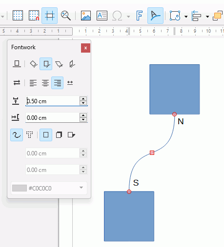
Strictly speaking, it possible using Fontwork (the one for putting text on a curve, not the one for distorting text). The problem is that you can fit only 1 line of words so you would have to have a predetermined number of spaces between N & S; if the connector were to be lengthened then the letters would be too far from the connecting objects, if the connector were to be shortened then the letters might be hidden underneath the objects they connect to.

  1. Click Tools > Customise > Toolbars find and select Fontwork (icon of an A on a curved line) and click the right-pointing arrow to add it to the Standard toolbar.
  2. Double click the connector to add text, type N lots of spaces then S.
  3. Click the Fontwork icon in the toolbar if Fontwork isn’t already open. then click the middle icon on the top row to place the text on the line. Make distance adjustments if needed. Click away to finish
  4. Copy connector to other objects

Any shape in Draw can have only one label. Consequently you must create a new “template shape” corresponding to your specification…

  1. create the bounding square
  2. create the N, E, S, W text boxes
  3. position the text boxes inside the bounding square
  4. group everything (and ideally give it a name in the Navigator)

Put the group aside for future usage.

When you need a tile for your map, duplicate the template shape and move it. Double-click to enter “label” mode to type its contents (like “Start”). Add the connectors, making sure they are really connectors, not simple lines (your screenshot shows non connected lines).

1 Like

In addition to @ajlittoz :

Connectors in Draw


In addition to @Grantler

The Gallery in LibreOffice

1 Like

In addition to other statements:

  • It is possible to drag “template drawings” into the gallery. When done you can use these shapes/objects as often as you like…
3 Likes

actually, the lines in my example ARE connectors, but they ended up connecting to the text boxes that are grouped with the square, instead of the square itself (because the boundary of the text box ended up outside the square.

Thanks for the response, though. Guess there’s no ‘easy’ answer :frowning:

I think it is easy. :grinning:
You must not group until you have created all connections.
Select the grouped elements and select “Ungroup”.


Example:
102962 HB Connectors.odg (11,2 KB)

well, that’s what I’m doing right now. It’s just a PITA, because that means I have to recreate this combined shape every single time.

Hmm… maybe I can add a ‘non-connected’ connector and then group it on my ‘template’ shape???

Instead of a document template, it is IMHO easier to use the gallery as suggested by @Grantler .
You can manage any number of objects or objects marked together in the gallery.
You can use the gallery in all components of LibreOffice.


For your procedure you can, for example, drag a square with a connector (marked together) into the gallery. If you right-click on this object in the gallery, you can select Insert.
On the worksheet, just select the connector and you can link it to another object.
I have deliberately not mentioned the inner designations here. You could insert the labels separately in the gallery and place them on the squares from there, like a kind of stamp.
When dragging objects into the gallery, make sure that you hold the object for approx. 2 seconds and only drag it into the gallery when the cursor changes.
Play a little with the available options. Good luck!

You can define alternate arrowhead shapes.

mapgrid.odg (24.9 KB) is a rough outline I made using that technique. Not sure whether the arrowhead styles for NSEW are embedded, but the letters converted to polygon shapes are part of the content, so you can create them by that recipe and add them again to the NorthSouth and EastWest line styles.

You will notice that the direction letters are on the box border, not inside. The best I can do is to center the shape on the glue point. For a better result you may want to add glue points inside the box. This requires that the box have a fill, but you can make that fill transparent. I didn’t put that effort into the creation.

2 Likes

Not embedded.

1 Like

You can combine a thin rectangle (or line) with the letter.
I don’t take the time to match lines width (and don’t know how to).
imagen
The nearest end of the rectangle must be at the center of the letter-rectangle shape.

1 Like